OVERVIEW:
In this article, you'll find the answers to all of the questions you ever had about Optical compression. We'll explain how optical compression works at an electrical level and why such a primitive circuit design is still so popular amongst its modern counterparts. Stick around to the end to see how opto compressors can often be the best choice in the studio.
TL/DR:
Optical compressors transform the audio signal into light by feeding part of the input signal into a light bulb. The light bulb flashes across a light-dependant resistor (LDR) in accordance with the audio it's receiving. The LDR then controls the amount of gain reduction which is proportionate to how much light it's receiving. Given that the light bulb and LDR have afterglow effects and warm-up times, this gives opto compression 'non-linearities' which sound very musical. This makes opto compression a popular choice on mix busses, bass guitars and vocals.
OPTO TYPOLOGY EXPLAINED:
The optical compressor works in a similar fashion to most other compressors. A signal feeds an amplifier circuit and also a control circuit, in this case, the control circuit is dictated by a light source. The light source in the early days used to be a light bulb with a fine filament, whereas these days an LED is a more reliable and accurate option. As the audio signal gets louder, the light bulb glows brighter, and as the signal diminishes, so too does the light. Capturing these fluctuations in light level is a light-dependent resistor (LDR). The LDR sits behind the amplifier circuit and controls the resistance of the outgoing signal. The greater the light glows, the more gain reduction, the less the light glows (or smaller the input signal), the less compression.
The greater the light shines, the less resistance there is for the LDR which means a greater voltage is subtracted (inverted) from the raw audio path in the op-amp.
As you’ll see pictured, most modern opto circuits still use an ‘op-amp’ to control gain in the amplifier circuit. A basic ‘op-amp’ has two inputs and one output. It works as a differential amplifier in that the output is proportional to the difference in voltage between the two inputs. So going into the first input (non-inverting input) will be the raw audio signal (blue signal). The second input (inverting input) is where the LDR comes into play. Given that the op-amp will output the difference between these two inputs, if there is no voltage coming in from the control circuit (red signal), then there is nothing to subtract from the raw audio. The raw audio signal is then free to pass straight to the output with no gain reduction applied. However, as soon as light starts hitting the LDR, resistance drops allowing current to flow and the signal begins to start flowing into the (inverting input) of the op-amp. Now the op-amp will invert the voltage it’s receiving from the control circuit with the raw audio, reducing gain and thus compressing the signal. The greater the light shines, the less resistance there is for the LDR which means a greater voltage is subtracted (inverted) from the raw audio path in the op-amp.
CHARACTERISTICS OF OPTO COMPRESSION:
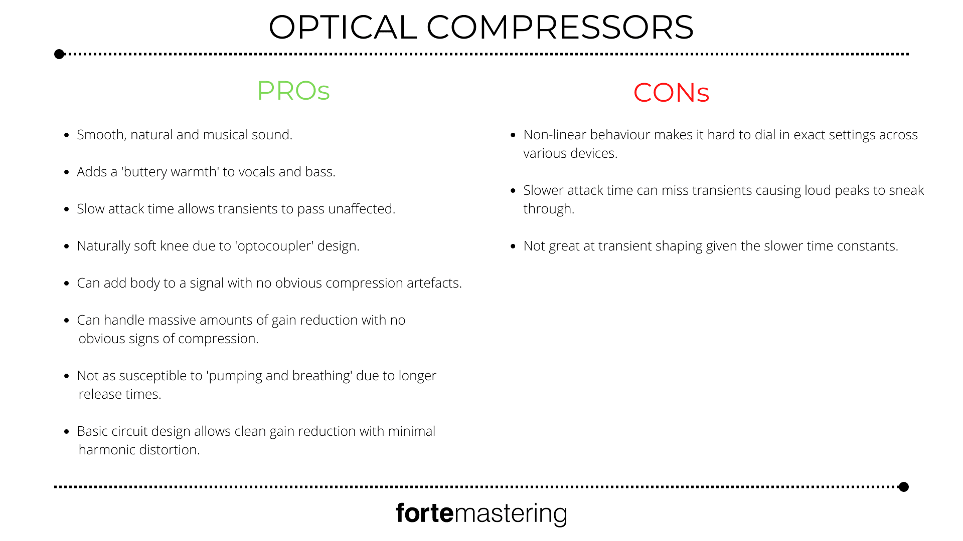
The way in which opto compressors use light to dictate their gain control gives way to various idiosyncrasies. Light is fast but the time it takes for a light bulb from glowing to full intensity may take more time than that of a FET transistor. This gives opto compressors a reputation for being much slower in their attack time. The other side to this is the non-linear nature of how light behaves on the LDR which causes many effects that have shown to be quite musical. This gives opto compressors some key characteristics that we’ll outline below.
NON-LINEAR:
The use of such analogue components invites inconsistencies and irregularities to occur within the interplay between the light source and the LDR. Furthermore, different units may use different light sources and different LDRs. Earlier models would make use of light bulbs with a filament which meant their attack time was compromised as the filament took time to heat up enough to glow. These days, LEDs are used due to their quicker response time and greater reliability. The same goes for the LDR components. The ‘T4 optical attenuator’ used in the original ‘LA-2A’ was both program and frequency-dependent causing the compression ratio to vary greatly based on what material it was fed. Therefore an optical compressor’s sonic behaviour is highly dependent on the materials used in its construction. This is similar to ‘Vari-MU’ style compression which we’ll cover in a later article.
The timing of the release therefore relies heavily on the strength and length of the incoming signal.
Perhaps most notably, optical compressors do not have constant or linear release times. The ‘LA-2A’ has an initial release time of around 60 milliseconds for the first 50% of the release time, the following 50% happens over several seconds before the signal reaches a fully uncompressed state again. The timing of the release therefore relies heavily on the strength and length of the incoming signal. These photocells exert a phenomenon called ‘memory’ where if the signal spends majority of its time in heavy compression above the threshold, then the release time will often be much longer. For example, keeping an opto compressor’s signal above the threshold will cause the circuit to infinitely compress as the release time extends. This can sound especially nice on mix busses when you need overall peak reduction and glue but don’t want to kill your transients.
MUSICAL:
The way in which optical compressors are constructed and the materials that they use lend a very musical aspect to them which keeps them very relevant. As discussed above, opto circuits have very non-linear ways of conducting business. For example, while the light striking an LDR is quick, it is not instantaneous. This means the attack time can lag a bit behind the raw signal. This is good if you want to leave punchy transients in place but still achieve a degree of compression. Because the compressor isn’t clamping down instantly on every transient that it comes across, the compression sounds much smoother, less jagged and more natural to our ears.
This means that the way the circuit is compressing audio is similar to the time constants that our ears would compress loud sounds in an open field.
The LDR used within opto compressors generally has a soft and gradual curve to their release. This means that the way the circuit is compressing audio is similar to the time constants that our ears would compress loud sounds in an open field. This makes optical compression very useful across mix busses as you can just skim across the top of a mix taking 1-3dB off the entire mix but in a very gentle and graceful way. Set it right and you can barely hear the 3dB you might be taking. Optical compression is also a popular choice for taming vocals since the gentle attack and release times seem to match quite well with the rise and fall of a vocal. In summation, it’s the gracefulness and ease of the optocoupler (Light and LDR) which create such musical compression. This allows them to handle more gain reduction, yet still sound natural and smooth.
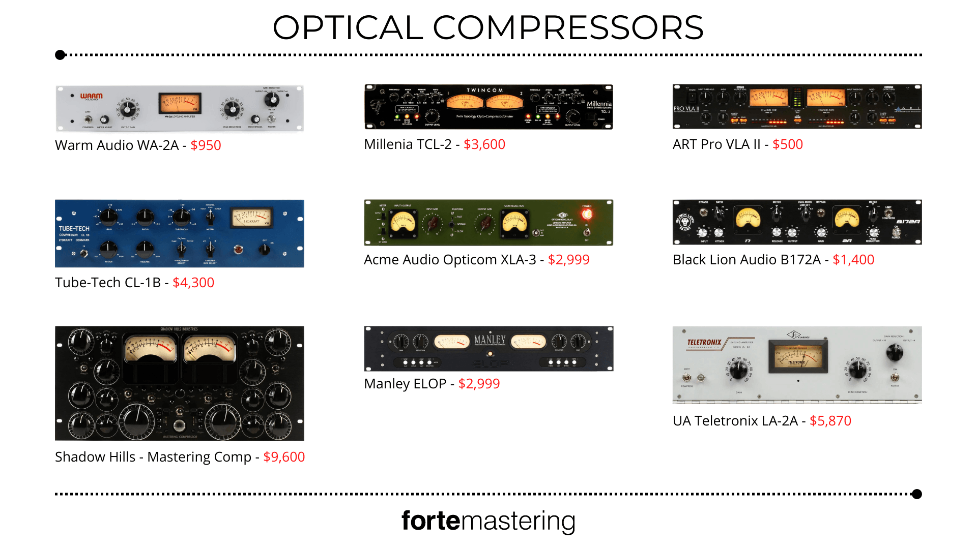
CLASSIC GEAR:
The optical compressor was invented by Jim Lawrence in the 1950s. Lawrence had a Military background working on optical sensors for the United States ‘Titan Missle Program’. During his time working as a Broadcast Engineer at KMGM in Los Angeles, he became frustrated with having to ride the gain to maintain a constant broadcast signal for air. In 1958, Lawrence founded ‘Teletronix Engineering’ where he went on to manufacture various broadcast equipment such as transmitter tubes, emergency tone generators and full-scale radio transmitters. His first levelling amplifier was called the LA-1. He then used his knowledge of photosensors to create an optical attenuator known as the ‘T4’ which he then placed in the upgraded LA-2. Engineers across the country began purchasing pairs of LA-2s (since each unit was only mono). They soon found their way into CBS, RCA and even the Ed Sulivan show. It wasn’t long before these compressors were showing up in recording studios around the country.
It wasn’t long before these compressors were showing up in recording studios around the country.
1962 saw the arrival of the LA-2A with upgrades to the faceplate, interior wiring and an improved noise floor. A solid-state version with a quicker attack and release time soon took form and was called the LA-3A. The LA-4A soon followed which offered even greater control over compression. Engineers began falling in love with the gentle character that the LA-2A gave to lead vocals. However as sales of the LA-2A began to slow, it was discontinued in 1969. It took 30 years later until Universal Audio did a full rebirth of the LA-2A in 1999. They were able to remodel the smooth and gentle character of the ‘T4′ photocell that was used back in the 60s. Universal Audio states that they’re now selling more of the hardware LA-2As than ever before. Despite the compressor design being 50 years old, engineers still turn to the buttery warmth that the LA-2A gives to vocals. You can hear this LA-2A input saturation on Jack White’s vocals on White Stripes’ Seven Nation Army. It adds this body that many modern pop artists and producers rely on to keep their records on top.